Machine Type: Philips Ultrasound
Machine Model: EPIQ5
Fault Phenomenon:
(1) The Philips EPIQ5 has been running relatively stably since its use, but recently, image artifacts have appeared. The main manifestations are slower equipment operation response, image whitening during scanning, coarsening of particles, especially frequent failures during abdominal and cranial scanning, and the appearance of double or multiple layers of images, with a significant decrease in image quality, as shown in Figure 1.
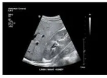
Figure 1
(1) First, consider whether it is a probe problem. Dust on the probe or poor circuit contact and poor heat dissipation can lead to a decrease in probe sensitivity, resulting in a decrease in image quality. At this time, you can switch to using the same model probe. If image artifacts are still found, further inspection is required. If the video connection from the workstation to the host has damaged outer skin, it is also very likely that poor image quality will occur. Therefore, it should be processed to eliminate the fault.
(2) The "time tag bad" prompt that appears in the image error is due to an error in the front-end synchronization signal, causing the image data packets sent from the front end to the back end to be disordered, thus resulting in image artifacts. Therefore, the focus of fault analysis is on the analog interface board and circuit board related to the front-end and clock.
(3) The purpose of the analog circuit board is to provide the initial clock signal to the front end of the machine and adjust the voltage of the front end. The main purpose of the analog interface board is to adjust the clock signal generated in the circuit board and communicate data between the front end and the back end in a timely manner to control the signal. Then, the front-end circuit board is detected through the internal COMMUNICATION software of the computer to determine whether the front-end clock is abnormal, that is, whether the circuit board is abnormal.
(4) Specifically: Through the machine front-end debugging port, connect an external computer through a data cable. Select the hyperterminal in the computer, and then receive the power-on circuit board's working information after the machine is powered on through the hyperterminal. The interface set for the hyperterminal includes COM1 and attributes, mainly 19200 bits per second, data flow control, stop bits, data bits, and parity check (none). The computer's hyperterminal interface can receive a series of data stream information related to the circuit board and display this information. If no error is reported, it indicates that the front-end clock is normal, that is, the circuit board is normal, so it can be determined that the interface board has failed, and then the problem of the interface board is solved to eliminate the fault.After the front-end and back-end clock synchronization signals are incorrect, the data packets obtained from the back end to the front end have a certain difference in time synchronization, resulting in image artifacts and clutter. Through the pulse Doppler intermittent report 206 system and probe error prompts, it can be understood that the clock signal usage is different from other modes; the probe uses a higher frame rate in cardiac measurement and relies on the clock. If the clock is incorrect, the probe cannot be used. This shows that when the system reports image quality problems, it is first necessary to pay attention to the initial equipment error report, check the corresponding system signal flow one by one, find the cause of the fault, and then formulate targeted solutions to eliminate the fault. Figure 2 shows the imaging of the EPIQ four-dimensional ultrasound after the fault is eliminated.
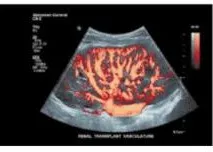
Figure 2
Through the above analysis and repair of the artifact fault of the Philips EPIQ5 four-dimensional ultrasound machine, we have a deeper understanding of its structure and improved our practical understanding, effectively increasing our confidence in repairing equipment. In order to effectively reduce faults, we have summarized the following points of experience: (1) Fully analyze and repair faults based on fault information prompts to improve machine repair efficiency.(2) Do regular maintenance and repair work, focusing on the heat dissipation system, regularly cleaning the air filter, and leaving a certain space at the air inlet and outlet of the ultrasound equipment to avoid poor heat dissipation, leading to equipment failure. (3) Train hospital engineers, especially in network transmission, image and video acquisition, etc.
This article is reprinted from the internet.
Please contact us to delete if there is any infringement.




